Project TN01000056/06 The optimization of energy piles for use the geothermal energy
Epile_2.0 Energy pile
Product number: TN01000056/06-V001
English synopsis: The Epile 2.0 software is intended for modeling the thermal-hydraulic behavior of foundation energy piles intended for exploiting the heat and cold of the building’s sub-base soil. The software is based on the numerical solution of 2D rotationally symmetric heat conduction, with 1D heat transfer by flow in a fluid circuit, solved by the control volume method. The software enables energy pile design, assessment, parametric simulation and energy and financial optimization using a cost function.
Information about the software is available upon request via e-mail at sikula.o@vutbr.cz.
Printscreens of the software’s user interface as well as sample outputs are listed and commented below.

Uživatelské rozhraní softwaru Epile_2.0

Sample of generated computational geometry and computational mesh
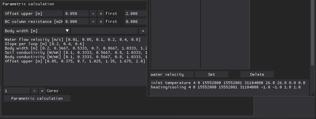
Example of parametric simulation settings
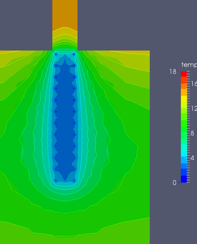
Sample results – temperature field in EP, soil and column at one time processed by Paraview software
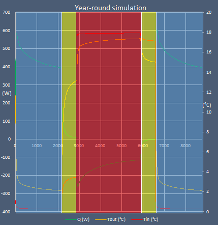
Example of results – course of selected temperatures and EP performances in the tested year – processed with MS Excel software.
EpMPF_2.0 Energy piles in method of load transfer functions
Product number: TN01000056/06-V002
English synopsis: The EpMPF 2.0 software is intended for the analysis of the force-deformation behaviour of a single large-diameter energy piles loaded both mechanically and thermally using the load-transfer method. Three types of load-transfer functions are available – hyperbolic, cubic parabola and cyclic. The program allows four types of analysis: 1. Mechanical loading (without the effect of temperature), 2. Thermal loading (only the effect of temperature), 3. Mechanical-thermal loading (combination of mechanical loading (force) in the pile head and monotonous or cyclic thermal loading) and 4. Mechanical-Thermal loading, ZP = 0 (combination of mechanical loading (force) in the pile head and monotonous thermal loading with prescribed zero displacement in the pile head).
Information on the software is available upon request via e-mail at mica.l@vutbr.cz.
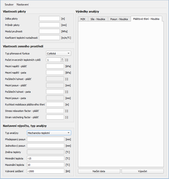
The working middle application is divided into four basic parts: a) Properties of the pile; b) Features of the terrestrial environment; c) Calculation settings and type of analysis; d) Results.Examples of the described software are shown in the following figures 1 to 3:
EpMPF 2.0 software graphical environment
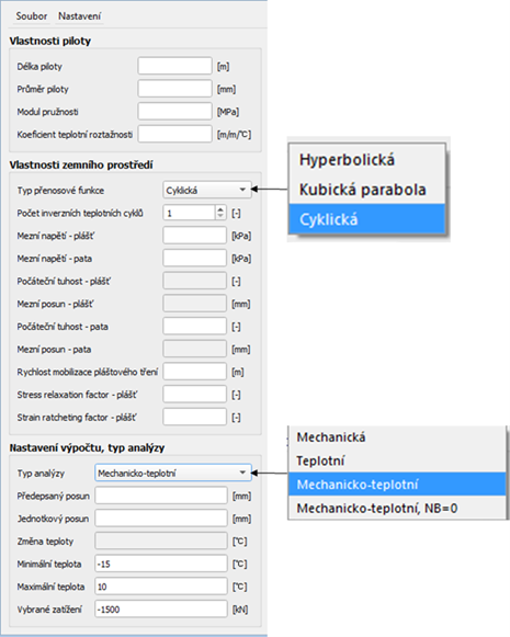
Graphical environment of EpMPF 2.0 software – section “Entering input parameters”. Note: The input fields are active according to the type of transfer function and type of analysis.
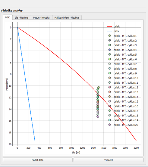
EpMPF 2.0 Software Graphical Environment – Section “Analysis Results – MZK (Limited Load Curve)”
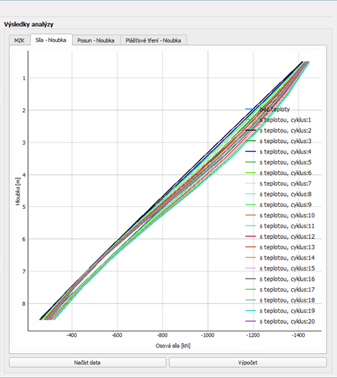
EpMPF 2.0 Software Graphical Environment – Section “Analysis Results – Axial Force – Depth)”
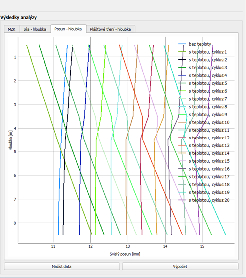
EpMPF 2.0 Software GUI – Section “Analysis Results – Vertical Displacement – Depth)”
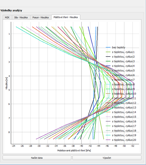
EpMPF 2.0 Software Graphical Environment – Section “Analysis Results – Mobilized Casing Friction – Depth)”
ZFMEpile 1.0
Product number: TN01000056/06-V003
English synopsis: The functional sample was designed within the framework of the project “Optimization of energy pilots for the use of earth energy” (TA CR, TN01000056 / 06). It is an experimental device that is designed to test single axially loaded energopile under laboratory conditions. The load cone together with the pressure system is used to simulate the state of stress around the pile. To simulate the temperature (+5°C ¸ + 40°C) stress, the system is supplemented by a temperature system (temperature changes can be simulated through the pile itself, through the base of the cone, or through a tubular heat exchanger installed inside the model). The functional sample is designed to evaluate the effect of temperature changes around the energopile on its vertical bearing capacity.
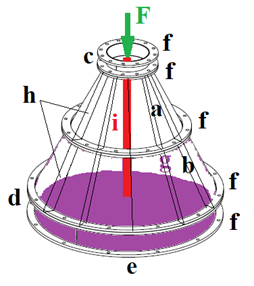
Diagram of the load cone: a) upper part of the cone, b) lower part of the cone, c) upper cylindrical superstructure, d) lower cylindrical superstructure, e) base plate (bottom of the cone), f) flanges, g) flexible rubber membrane, h) reinforcements shell of the cone, i) energopile model, P – water pressure on the membrane, F – axial compressive force in the head of the pile model, σv – theoretical course of vertical stress in the axis of the cone, σH – theoretical course of horizontal stress in the axis of the cone [dimensions in mm].
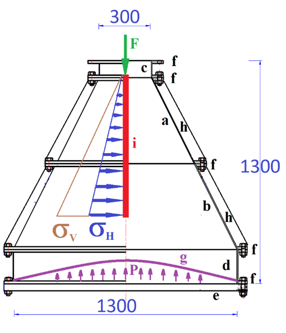
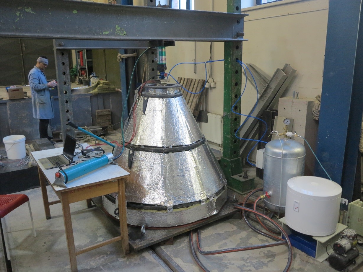
Photo of the prototype of load cone